
Introduction
After leaving the Toucan’s door behind, the trail leads you to a peaceful mountain.
On a branch, a sloth yawns and says in a calm voice:
“No need to rush… To reach the top you can use trail A or trail B.
If either one is open, you’ll get there. And if both are open, you will too! Here we use OR logic.”
Your mission is to verify this behavior in the simulator and light up the path to the top.

What is the OR gate?
- It has two inputs and one output.
- The output turns on (
1) if at least one of the inputs is on (1). - It only stays off (
0) when both inputs are off (0).
See full truth table
| Input A | Input B | OR Output |
|---|---|---|
| 0 | 0 | 0 |
| 0 | 1 | 1 |
| 1 | 0 | 1 |
| 1 | 1 | 1 |

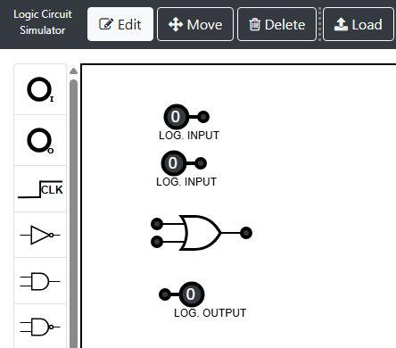
Simulator instructions
1. Place the components
- Make sure you are in Edit mode.
- In the left sidebar, select and place:
- Input ➔ place two inputs (A and B).
- OR Gate ➔ place an OR gate between the inputs and the output.
- Output ➔ place an output to the right of the gate.
2. Connect the components
- Connect the output of Input A to one of the OR gate inputs.
- Connect the output of Input B to the other input of the OR gate.
- Connect the output of the OR gate to the Output.
3. Test the circuit
- Click on each Input to toggle
0↔1. - Try all four combinations (00, 01, 10, 11).
- Goal / Victory condition: the output should be
1if A = 1 or B = 1 (or both).
“See? With just one open path, you can already make it to the top.”
Quick tips
- If the output stays at
0even with A = 1 or B = 1, check that both inputs are connected to the OR gate. - Verify that you used OR Gate and not AND Gate by mistake.
Simulator
What did you learn?
- OR represents options: just one path is enough to activate the output.
- The only way for the output to be
0is if A = 0 and B = 0 at the same time.
Next up
In the next activity, you will visit the reflection pond with the Frog and discover how the NOT gate works.